Monday, 20 June 2016

Testing LifeCycle in the Telecom Industry

The Test Lifecycle in the telecom industry is similar to that of any other industry but with a stress on details. Here is how the test lifecycle looks like along with the test artifacts.
Telecom Testing Stage
Test artifacts
  • Business View
  • Requirement based test artifacts
  • Feasibility based artifacts
  • Standard and policy identification based test artifacts
  • Operation and maintenance considerations related test artifacts
  • System/ Architecture
  • System test artifacts (Security, Installation)
  • Test artifacts for virtual prototype
  • Special system testing artifacts ( interoperability, disaster recovery)
  • Implementation
  • Unit test artifacts
  • Integration test artifacts
  • Quality and performance artifacts
  • Regression, load testing, sanity, etc.
  • Deployment
  • Acceptance test artifacts
  • Integration test artifacts
  • Quality and performance artifacts
  • Functional test artifacts
  • Alpha/Beta test artifacts

Types of Testing Performed on Telecom Software

  • Interconnection Testing
  • Conformance Testing
  • IVR Testing
  • Performance Testing
  • Security Testing
  • Interoperability Testing
  • Protocol Testing
  • Functional Testing
  • Automation Testing

Sample TestCases for Telecom Testing

In Telecom Testing, one must consider testing following
Various Telecom Testing
Testing activities in Telecom
Billing System
  • Verify, the telephone number of the customer, is registered under telecom operator
  • Verify whether number is still working
  • Verify the number entered is valid, and it is 10 digit number
  • Verify the number is not blocked due to some reasons
  • Verify if the number has any outstanding bills, if exist, display it on screen
  • Verify the number has all previous accounts or bills cleared
  • Verify the system enables statement generation as per customer requirement
  • Verify the system has recorded number of calls accurately
  • Verify the plan chosen by the customer displays on the billing system
  • Verify the total amount billed is accurate and mapped to the service offered
Application Testing
  • Protocols, signaling, field testing for IOT
  • Usage and functional testing for core mobile handset applications like call, SMS, transfer/hold, etc.
  • Testing of various applications like finance, sports and location based services, etc. OSS-BSS testing
OSS-BSS Testing
  • Billing, customer case, interconnect billing, order and fraud management, revenue assurance
  • Network management, mediation, provisioning, etc.
  • EAI, CRM & ERP, data warehousing, etc.
Conformance Testing
  • Electrical interface compatibility
  • Conformance of protocol
  • Conformance of transport layers
IVR Testing
  • Interactive test scenarios
  • Detection of voice energy
  • Broadband audio tones
  • Extensive conditional branching sequences
  • DTMF Entries
Summary
The telecom service is a very broad field consists of various component including cables, networks, signals, protocols, etc. and their testing requires broad range of testing techniques, so the choice of testing techniques and strategy highly depends on what component of telecom is tested.
The test requirement, scope, test scenarios, testing techniques, testing tools, etc. varies with the type of testing involves, it can be protocol testing for VoIP or wireless device testing for CDMA. The tutorial gives basic but complete overview of how telecom testing can be performed and discuss various prospects that are crucial for telecom testing.

Testing Telecom Application with Sample Testcases

Since the shift of telecom sector to computer network and digital medium, telecommunication sector has undergone a major software transformation. Telecom started depending on the various types of software components to deliver many services like routing and switching, VoIP broadband access, etc. Hence, that telecom testing has become an inevitable process.
In this tutorial, we will learn-

What is Domain in Testing?

Domain is nothing but the industry for which the software testing project is created. When we talk about software project or development, this term is often referred. For example, Insurance domain, Banking domain, Retail Domain, Telecom Domain, etc.

Why Domain Knowledge Matters?

Domain knowledge is quintessential for testing any software product, and it has its own benefits like

Business Processes in Telecom Industry

For telecom testing end-to-end service verification is important. To ensure efficient testing a good understanding of different Business process is a must.
You need to understand each stage of service deliverability before drafting the test cases.
Telecom services are either based on a business support system that includes IVR's, Call Centers, generating invoices, etc. or an operation support system that includes routers, switches, cell towers, etc.
The following table shows what activities are performed at different levels
Telecom DepartmentTelecom Activities
Pre-sales
  • It handles all the sales information like discounts, services, promos, etc.
Ordering
  • Applying for a new connection or disconnecting a connection
Provisioning
  • This division deals with the physical connection between customers and TSP ( Telecom Service Provider)
Billing
  • Under this division, all billing work is done
Service Assurance
  • In case of any failure, this division corrects the problem
Inventory Systems
  • It is the repository of all information
Tracking
  • This division tracks the ordering system and the status of an order

Typical Telecom Business Process

Following is a typical business process in the Telecom Industry.

Types of Protocols used in Telecom Industry

Here the popular protocols used in the Telecom industry
  • VoIP technologies: VoIP, IMS, MPLS, ISDN, PSTN
  • Signaling and Protocols: SIP, ISDN, Codecs, H.323
  • Wireless technologies: GPRS, CDMA, GSM, UMTS
  • Network Management: SNMP
  • Layer 2 Protocols: ARP, STP, L2TP, PPP
  • Layer 3 protocols/routing: ICMP, BGP, ISIS, MPLS
  • Infrastructure/Security: ATM, TCP/IP, LAN/VLAN, SSH
You can learn more about Protocol Testing here

Tools for protocol testing

Tools for Protocol Testing

Lets discuss the most important testing tools used to verify protocols

Scapy For Packet Crafting

Scapy is a powerful interactive packet manipulation program. It enable you to
  • Create packets
  • Decode packets on the network
  • Capture packets and analyze them
  • Inject packets into the network
So, basically scapy mainly does two things: receiving answers and sending packets. You define the packets, it sends them, receives answers, match requests with answers and returns a list of packet couples and a list of unmatched packets.
It can also handle other things as well like trace-routing, unit tests, attacks or network discovery, developing new protocols, probing, etc.
Scapy enable us to write a python script that allow us to perform a task like sending and receiving packets or sniffing packets. For example, scapy can sniff the data packet by using python script. The command to open the getdit entered in the editor
#gedit scapysniff.py
#!/usr/bin/env python
from scapy.all import*
a= sniff(count=10)
a.nsummary()
save, and change the mode of the file into an executable form
#chmod+x scapysniff.py
# ./scaotsbuff.py
It will sniff 10 packets and soon as it has sniffed 10 packets it will print the summary. Scapy also as an array of command for sending and receiving packets at the same time
Download Scapy

Wireshark Tools For Analysis

Tools used for protocol testing- WireShark . It allows to capture packets in real time and display them in human readable form. It allows you to dig deep into the network traffic and inspect individual packets by using color coding and filters.
Wireshark captures packets that helps to determine when the session is getting established, when the exact data travel was initiated and how much data is sent each time, etc.
Wireshark has a set of rich features which includes
  • Thorough inspection of hundreds of protocols, more being added all the time
  • Live capture and offline analysis
  • Rich VoIP analysis
  • Standard three pane packed browser
  • Runs on multi-platforms like Windows, Linux, OSX and so on
  • Captured network data can be browsed via a GUI
  • Decryption support many protocols like IPsec, ISAKMP, SSL/TLS
  • Live data can be read from Ethernet, ATM, Bluetooth, USB, token etc.
  • Output can be exported to CSV, XML, plain text, etc.
Download Wireshark

TTCN

TCCN is a standard testing language for defining test scenario and their implementation for protocol testing. A TCCN test suite contains many test cases written in the TTCN programming language and it is used for testing reactive systems or behavioral testing.
For example, a coffee vending machine that gives you coffee on inserting a dollar coin but does not respond if anything less than dollar in inserted into it. To program such machines TCCN3 language is used. In order to make coffee machine responds when inserting a coin we have to write TCCN-3 component that behaves as a coffee machine. It allow us to run our test before actual coffee machine is available as a product. Once it is done we will connect the TCCN3 test suite with the external device.
The test system emits stimuli (dollar coin) and receives responses (coffee). The stimuli adapter obtains stimuli from the test system and passes them to the system under test. The response adapter waits for responses of the system under test and passes them to the test system.
TCCN3 can be used in various fields like
  • Mobile communications (LTE, WIMAX, 3G etc)
  • Broadband technologies (ATM,DSL)
  • Middleware Platforms (Webservices, CORBA etc)
  • Internet Protocol ( SIP, IMS, IPv6)
  • Smart Cards
  • Automative (AutoSAR, MOST, CAN)
In TCCN we can define
  • Test Suites
  • Test Cases
  • Test Steps
  • Declare Variables
  • Declare Timers
  • Create PDUs etc.
TCCN can be integrated with types systems of other languages like ASN.1, XML , C/ C++ . TCCN3 core language exists in text format apart from other format like tabular, graphical and presentation.

Sample Test Cases for Protocol Testing of Network Devices

Test NameTest Cases
  1. 1VLAN on 1 Switch
  • Build two different VLANs. Check the visibility between hosts on different VLANs
  1. 3Symmatric VLANs on 1 switch
  • Create three different asymmetric VLANs. Check the visibility between hosts
  1. Spanning Tree: Root Path Cost Variation
  • Test how the Root Path Cost changes after a topology variation
  1. Spanning Tree: Port Blocking
  • Check how spanning tree protocol avoids formation of cycles in the network, blocking redundant links, in presence of VLANs too
  1. Different Root Bridge for Different MSTI
  • Show that each MSTI can have different Root Bridge
  1. Visibility between different STP Regions
  • With same VLANs check visibility between different STP regions
  1. Telephone switch Performance
  • Generate 1000 telephone calls and check whether the telephone switch still operates or its performance degrades
  1. Negative test for device
  • Enter the incorrect key and check the user for authentication. It should not allow user to access
  1. Line speed
  • Check the device operating at 10Gbps speed, utilizing all the available bandwidth to handle incoming traffic
  1. Protocol conversation rate
  • Track a TCP conversation between two devices and verify that each device engaged in a correct behavior
  1. Response time for session initiation
  • Measure the response time of a device to an invite request for session initiation

Protocol Testing

What is Protocol in a software industry?

When computer communicates with each other, there is a common set of rules and conditions that each computer has to follow. In other words, protocols determine how data are transmitted between computing devices and over networks.
Protocols are classified into two categories routed protocols and a routing protocols
  • Routed Protocols: Routed protocols can be used to send the user data from one network to another network. It carries user traffic like e-mails, web-traffic, file transfers, etc. Routed protocols are IP, IPX, and AppleTalk.
  • Routing Protocols: Routing protocols are network protocols that determine routes for routers. It is only used between routers. For example RIP, IGRP, EIGRP, etc.
In simple terms, router is like a bus used for transportation while routing protocols are signals on the road.
Based on the type of communication different protocols are used.
In this tutorial we will learn

Types of computer protocols

Types of ProtocolsPurpose of Protocols
TCP/IP It is used to send information in small packets over Internet
UDP/ ICMPIt is used to send small amount of information in data-packets over internet
POP3 and SMTPIt is used for sending and receiving mail
Hypertext Transfer ProtocolIt is used to transfer HTML page in encrypted form to provide security to sensitive data
FTP It is used for transporting files over a network from one node to another
* TCP/IP- Transmission Control Protocol/ Internet protocol, UDP / ICMP- User Datagram Protocol/Internet Control Message Protocol, POP3/SMTP- Post Office Protocol / Simple Mail Transfer Protocol, HTTP- Hyper Text Transfer Protocol, FTP- File Transfer Protocol

Different types of network Protocols (L2 and L3)

The OSI model has total 7 layer of network communication, in which layer 2 and layer 3 are very crucial.
  • Layer 2: It is a data link layer. Mac address, Ethernet, Token Ring, and Frame Relay are all examples of Data link layer.
  • Layer 3: It is a network layer that determines the best available path in the network for communication. IP address is an example of layer3.

What is Protocol Testing?

Protocol testing is a generic term used by companies working in the communication industry for testing different protocols in domains of Switching, Wireless, VoIP, Routing, Switching, etc.
Companies like CISCO, JUNIPER, ALCATEL produce networking devices like routers, modems, wireless access points, etc. that use different protocols for communication, for example, CISCO uses EIGRP, OSPF, etc.
Protocol testing is nothing but checking whether EIGRP (Enhanced Interior Gateway Routing Protocol) or OSPF (Open Shortest Path First) or any other protocol is working as per respective standard.

Protocol Testing Process

  • For protocol testing, you need protocol analyzer and simulator
  • Protocol analyzer ensures proper decoding along with call and session analysis. While simulator simulates various entities of networking element
  • Usually a protocol testing is carried out by DUT (device under test) to other devices like switches and routers and configuring protocol in it
  • Thereafter checking the packet structure of the packets send by the devices
  • It checks scalability, performance, protocol algorithm etc. of the device by using tools like lxNetworks, Scapy and Wireshark

Testing Types for Protocol Testing

Protocol testing includes testing of functionality, performance, protocol stack, interoperability, etc. During protocol testing basically three checks is done.
  • Correctness: Do we receive packet X when we expected
  • Latency: How long does a packet take to transit the system
  • Bandwidth: How many packets we can send per second
Protocol testing can be segregated into two categories. Stress and Reliability Tests and Functional Tests. Stress and Reliability tests cover load testing, stress testing, performance testing, etc. While functional testing includes negative testing, conformance testing, interoperability testing, etc.
  • Conformance Testing: The protocols implemented on products are tested for adherence like IEEE, RFC etc.
  • Interoperability Testing: The interoperability for different vendors are tested. This testing is done after conformance testing is done on the appropriate platform
  • Network feature Testing: The features on networking products are tested for functionality with reference to the design document. For example features can be port-security on a switch, ACL on a router etc.


Wednesday, 9 March 2016

Google 5G concept

Google's Project SkyBender aims to beam 5G internet from solar-powered drones 

Google is working in secret at a spaceport in New Mexico to build and test solar-powered internet drones in a new initiative codenamed Project SkyBender, according to a report from The Guardian today. The company is reportedly renting 15,000 square feet of hangar space from Virgin Galactic — the commercial spaceflight outfit of business mogul Richard Branson — at the privately owned Spaceport America located near a town called Truth or Consequences. The lynchpin of Project SkyBender appears to be cutting-edge millimeter wave technology, which can transmit gigabits of data every second at speeds up to 40 times faster than modern 4G LTE.
Millimeter waves are thought to be the future of high-speed data transmission technology, and may form the backbone of 5G mobile networks. Aereo founder Chet Kanojia's new startup Starry announced earlier this week it would use millimeter wave tech to bring gigabit internet speeds to people's homes via Wi-Fi. Millimeter waves have much shorter range than current smartphone signals and are easily disrupted by weather conditions like rain, fog, and snow. Using what's called a phased array, however, Google and others could potentially focus the transmissions over greater distances.
Google is using millimeter wave technology to achieve 5G speeds
Google is currently testing the technique with a new solar-powered drone called Centaur and other units made by a division known as Google Titan, which the company formed after it acquired drone maker Titan Aerospace in 2014. The company has a deal with the FCC to continue testing until July, according to The Guardian. It's also paying Virgin Galactic about $1,000 a day to use its hanger, as well as an additional $300,000 to Spaceport America to construct installations with servers, millimeter wave transceivers, and other tech onsite.
Google has noted in the past how it plans to compete with other tech giants like Facebook to bring internet access to developing countries. The Guardian says SkyBender is technically part of Google Access, a division that houses Project Loon, Google's air balloon Wi-Fi project aimed at a similar goal of bringing remote parts of the world online. Google did not respond to a request for comment.


Telecom cloud

                            Telecom cloud

Cloud Computing In Telecommunication

Cloud communications are Internet-based voice and data communications where telecommunications applications, switching and storage are hosted by a third-party outside of the organization using them, and they are accessed over the public Internet. Cloud services is a broad term, referring primarily to data-center-hosted services that are run and accessed over an Internet infrastructure. Until recently, these services have been data-centric, but with the evolution of VoIP (voice over Internet protocol), voice has become part of the cloud phenomenon. Cloud telephony refers specifically to voice services and more specifically the replacement of conventional business telephone equipment, such as a Private branch exchange (PBX), with third-party VoIP service.
Cloud communications providers deliver voice & data communications applications and services, hosting them on servers that the providers own and maintain, giving their customers access to the “cloud.” Because they only pay for services or applications they use, customers have a more cost-effective, reliable and secure communications environment, without the headaches associated with more conventional PBX system deployment.
Companies can cut costs with cloud communications services without sacrificing features. The success of Google and others as cloud-based providers has demonstrated that a cloud-based platform can be just as effective as a software-based platform, but at a much lower cost. Voice services delivered from the cloud increases the value of hosted telephony, as users can equally well turn to a cloud-based offering instead of relying on a facilities-based service provider for hosted VoIP. This expands their options beyond local or regional carriers.
In the past, businesses have been able to do this for IT services, but not telecom. Cloud communications is attractive because the cloud can now become a platform for voice, data and video. Most hosted services have been built around voice, and are usually referred to as hosted VoIP. The cloud communications environment serves as a platform upon which all these modes can seamlessly work as well as integrate.
There are three trends in enterprise communications pushing users to access the cloud and allowing them to do it from any device they choose, a development traditional IT communications infrastructure was not designed to handle. The first trend is increasingly distributed company operations in branches and home offices, making WANs cumbersome, inefficient and costly. Second, more communications devices need access to enterprise networks – iPhones, printers and VoIP handsets, for example. Third, data centers housing enterprise IT assets and applications are consolidating and are often being located and managed remotely.
Ericsson r


Tuesday, 8 March 2016

Introducing LTE-Advanced

Introducing LTE-Advanced

Application Note
LTE-Advanced (LTE-A) is the project name of the evolved version of LTE that is
being developed by 3GPP. LTE-A will meet or exceed the requirements of the
International Telecommunication Union (ITU) for the fourth generation (4G) radio
communication standard known as IMT-Advanced. LTE-Advanced is being speci-
fied initially as part of Release 10 of the 3GPP specifications, with a functional
freeze targeted for March 2011. The LTE specifications will continue to be
developed in subsequent 3GPP releases.
In October 2009, the 3GPP Partners formally submitted LTE-Advanced to the
ITU Radiocommunication sector (ITU-R) as a candidate for 4G IMT-Advanced [1].
Publication by the ITU of the specification for IMT-Advanced is expected by
March 2011. As more and more wireless operators announce plans to deploy
LTE in their next-generation networks, interest in LTE-Advanced is growing.
This application note covers the following topics:
• Summary of the ITU requirements for 4G
• Summary of 3GPP requirements for LTE-Advanced, including the expected
timeline
• Key solution proposals for LTE-Advanced
• Release 10 and beyond: Technologies under consideration
• Anticipated design and test challenges
The application note also introduces Agilent’s LTE-Advanced design and test
solutions that are ready for use by early adopters. These solutions will be con-
tinuously enhanced as the LTE-Advanced specifications are released.


Monday, 7 March 2016

LTE Advanced (LTE+)

With the standards definitions now available for LTE, the Long Term Evolution of the 3G services, eyes are now turning towards the next development, that of the truly 4G technology named IMT Advanced. The new technology being developed under the auspices of 3GPP to meet these requirements is often termed LTE Advanced.
In order that the cellular telecommunications technology is able to keep pace with technologies that may compete, it is necessary to ensure that new cellular technologies are being formulated and developed. This is the reasoning behind starting the development of the new LTE Advanced systems, proving the technology and developing the LTE Advanced standards.

Typical cellphone handsets that can operate on a 4G LTE-Advanced network
In order that the correct solution is adopted for the 4G system, the ITU-R (International Telecommunications Union - Radiocommunications sector) has started its evaluation process to develop the recommendations for the terrestrial components of the IMT Advanced radio interface. One of the main competitors for this is the LTE Advanced solution.
One of the key milestones is October 2010 when the ITU-R decides the framework and key characteristics for the IMT Advanced standard. Before this, the ITU-R will undertake the evaluation of the various proposed radio interface technologies of which LTE Advanced is a major contender.

Key milestones for ITU-R IMT Advanced evaluation

The ITU-R has set a number of milestones to ensure that the evaluation of IMT Advanced technologies occurs in a timely fashion. A summary of the main milestones is given below and this defines many of the overall timescales for the development of IMT Advanced and in this case LTE Advanced as one of the main technologies to be evaluated.

Key Milestones on the Development of 4G LTE-Advanced
Milestone Date
Issue invitation to propose Radio Interface Technologies. March 2008
ITU date for cut-off for submission of proposed Radio Interface Technologies. October 2009
Cutoff date for evaluation report to ITU. June 2010
Decision on framework of key characteristics of IMT Advanced Radio Interface Technologies. October 2010
Completion of development of radio interface specification recommendations. February 2011

LTE Advanced development history

With 3G technology established, it was obvious that the rate of development of cellular technology should not slow. As a result initial ideas for the development of a new 4G system started to be investigated. In one early investigation which took place on 25 December 2006 with information released to the press on 9 February 2007, NTT DoCoMo detailed information about trials in which they were able to send data at speeds up to approximately 5 Gbit/s in the downlink within a 100MHz bandwidth to a mobile station moving at 10km/h. The scheme used several technologies to achieve this including variable spreading factor spread orthogonal frequency division multiplex, MIMO, multiple input multiple output, and maximum likelihood detection. Details of these new 4G trials were passed to 3GPP for their consideration
In 2008 3GPP held two workshops on IMT Advanced, where the "Requirements for Further Advancements for E-UTRA" were gathered. The resulting Technical Report 36.913 was then published in June 2008 and submitted to the ITU-R defining the LTE-Advanced system as their proposal for IMT-Advanced.
The development of LTE Advanced / IMT Advanced can be seen to follow and evolution from the 3G services that were developed using UMTS / W-CDMA technology.

Comparison of LTE-A with other Cellular Technologies
  WCDMA
(UMTS)
HSPA
HSDPA / HSUPA
HSPA+ LTE LTE Advanced
(IMT Advanced)
Max downlink speed
bps
384 k 14 M 28 M 100M 1G
Max uplink speed
bps
128 k 5.7 M 11 M 50 M 500 M
Latency
round trip time
approx
150 ms 100 ms 50ms (max) ~10 ms less than 5 ms
3GPP releases Rel 99/4 Rel 5 / 6 Rel 7 Rel 8 Rel 10
Approx years of initial roll out 2003 / 4 2005 / 6 HSDPA
2007 / 8 HSUPA
2008 / 9 2009 / 10 2014 / 15
Access methodology CDMA CDMA CDMA OFDMA / SC-FDMA OFDMA / SC-FDMA
LTE Advanced is not the only candidate technology. WiMAX is also there, offering very high data rates and high levels of mobility. However it now seems less likely that WiMAX will be adopted as the 4G technology, with LTE Advanced appearing to be better positioned.

LTE Advanced key features

With work starting on LTE Advanced, a number of key requirements and key features are coming to light. Although not fixed yet in the specifications, there are many high level aims for the new LTE Advanced specification. These will need to be verified and much work remains to be undertaken in the specifications before these are all fixed. Currently some of the main headline aims for LTE Advanced can be seen below:
  1. Peak data rates: downlink - 1 Gbps; uplink - 500 Mbps.
  2. Spectrum efficiency: 3 times greater than LTE.
  3. Peak spectrum efficiency: downlink - 30 bps/Hz; uplink - 15 bps/Hz.
  4. Spectrum use: the ability to support scalable bandwidth use and spectrum aggregation where non-contiguous spectrum needs to be used.
  5. Latency: from Idle to Connected in less than 50 ms and then shorter than 5 ms one way for individual packet transmission.
  6. Cell edge user throughput to be twice that of LTE.
  7. Average user throughput to be 3 times that of LTE.
  8. Mobility: Same as that in LTE
  9. Compatibility: LTE Advanced shall be capable of interworking with LTE and 3GPP legacy systems.
These are many of the development aims for LTE Advanced. Their actual figures and the actual implementation of them will need to be worked out during the specification stage of the system.

LTE Advanced technologies

There are a number of key technologies that will enable LTE Advanced to achieve the high data throughput rates that are required. MIMO and OFDM are two of the base technologies that will be enablers. Along with these there are a number of other techniques and technologies that will be employed.
  • Orthogonal Frequency Division Multiplex, OFDM   OFDM forms the basis of the radio bearer. Along with it there is OFDMA (Orthogonal Frequency Division Multiple Access) along with SC-FDMA (Single Channel Orthogonal Frequency Division Multiple Access). These will be used in a hybrid format. However the basis for all of these access schemes is OFDM.

    Note on OFDM:

    Orthogonal Frequency Division Multiplex (OFDM) is a form of transmission that uses a large number of close spaced carriers that are modulated with low rate data. Normally these signals would be expected to interfere with each other, but by making the signals orthogonal to each other there is no mutual interference. The data to be transmitted is split across all the carriers to give resilience against selective fading from multi-path effects..
    Click on the link for an OFDM tutorial

  • Multiple Input Multiple Output, MIMO:   One of the other key enablers for LTE Advanced that is common to LTE is MIMO. This scheme is also used by many other technologies including WiMAX and Wi-Fi - 802.11n. MIMO - Multiple Input Multiple Output enables the data rates achieved to be increased beyond what the basic radio bearer would normally allow.

    Note on MIMO:

    Two major limitations in communications channels can be multipath interference, and the data throughput limitations as a result of Shannon's Law. MIMO provides a way of utilising the multiple signal paths that exist between a transmitter and receiver to significantly improve the data throughput available on a given channel with its defined bandwidth. By using multiple antennas at the transmitter and receiver along with some complex digital signal processing, MIMO technology enables the system to set up multiple data streams on the same channel, thereby increasing the data capacity of a channel.
    Click on the link for a MIMO tutorial


    For LTE Advanced, the use of MIMO is likely to involve further and more advanced techniques including the use of additional antennas in the matrix to enable additional paths to be used, although as the number of antennas increases, the overhead increases and the return per additional path is less.

    In additional to the numbers of antennas increasing, it is likely that techniques such as beamforming may be used to enable the antenna coverage to be focused where it is needed.
  • Carrier Aggregation, CA:   As many operators do not have sufficient contiguous spectrum to provide the required bandwidths for the very high data rates, a scheme known as carrier aggregation has been developed. Using this technology operators are able to utilise multiple channels either in the same bands or different areas of the spectrum to provide the required bandwidth. Read more about Carrier Aggregation, CA
  • Coordinated Multipoint :   One of the key issues with many cellular systems is that of poor performance at the cell edges. Interference from adjacent cells along with poor signal quality lead to a reduction in data rates. For LTE-Advanced a scheme known as coordinated multipoint has been introduced. Read more about Coordinated Multipoint, CoMP
  • LTE Relaying:   LTE relaying is a scheme that enables signals to be forwarded by remote stations from a main base station to improve coverage. Read more about LTE Relaying
  • Device to Device, D2D:   LTE D2D is a facility that has been requested by a number of users, in particular the emergency services. It enables fast swift access via direct communication - a facility that is essential for the emergency services when they may be on the scene of an incident. Read more about Device to Device communications

LTE Technology Leyers

LTE video tutorial


LTE physical layer


Introduction to LTE architecture


LTE network architecture

E-UTRAN user plance protocol stack

EPS architecture overview

This excellent video by Russell DeLong covers the EPS in detail. The topics covered here are:
Terminology clarifications for "4G LTE" and the EPS.
Overview of each component of EPS. Russell walks you through the role of the MME, the S-GW and the P-GW.
Overview of each logical connection between each component on the EPS.

LTE channels and protocol layers


LTE physical layer presentation


Thursday, 3 March 2016

LTE ( 4G ) Optimisation and R&d: LTE INTRODUCTION

LTE ( 4G ) Optimisation and R&d: LTE INTRODUCTION: INTRODUCTION TO LTE....... LTE stands for Long Term Evolution and it was started as a project in 2004 by telecommunication body kno...

Wednesday, 2 March 2016

LTE Glossary

LTE Glossary

Term Description
3GPP 3rd Generation Partnership Project
3GPP2 3rd Generation Partnership Project 2
ARIB Association of Radio Industries and Businesses
ATIS Alliance for Telecommunication Industry Solutions
AWS Advanced Wireless Services
CAPEX Capital Expenditure
CCSA China Communications Standards Association
CDMA Code Division Multiple Access
CDMA2000 Code Division Multiple Access 2000
DAB Digital Audio Broadcast
DSL Digital Subscriber Line
DVB Digital Video Broadcast
eHSPA evolved High Speed Packet Access
ETSI European Telecommunications Standards Institute
FDD Frequency Division Duplex
FWT Fixed Wireless Terminal
GSM Global System for Mobile communication
HSPA High Speed Packet Access
HSS Home Subscriber Server
IEEE Institute of Electrical and Electronics Engineers
IPTV Internet Protocol Television
LTE Long Term Evolution
MBMS Multimedia Broadcast Multicast Service
MIMO Multiple Input Multiple Output
MME Mobility Management Entity
NGMN Next Generation Mobile Networks
OFDM Orthogonal Frequency Division Multiplexing
OPEX Operational Expenditure
PAPR Peak to Average Power Ratio
PCI Peripheral Component Interconnect
PCRF Policing and Charging Rules Function
PDSN Packet Data Serving Node
PS Packet Switched
QoS Quality of Service
RAN Radio Access Network
SAE System Architecture Evolution
SC-FDMA Single Carrier Frequency Division Multiple Access
SGSN Serving GPRS Support Node
TDD Time Division Duplex
TTA Telecommunications Technology Association
TTC Telecommunication Technology Committee
TTI Transmission Time Interval
UTRA Universal Terrestrial Radio Access
UTRAN Universal Terrestrial Radio Access Network
WCDMA Wideband Code Division Multiple Access
WLAN Wireless Local Area Network


LTE OFDM Technology

LTE OFDM Technology

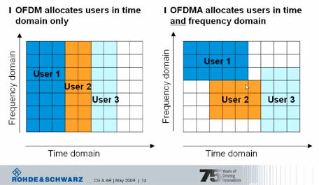
To overcome the effect of multi path fading problem available in UMTS, LTE uses Orthogonal Frequency Division Multiplexing (OFDM) for the downlink - that is, from the base station to the terminal to transmit the data over many narrow band careers of 180 KHz each instead of spreading one signal over the complete 5MHz career bandwidth ie. OFDM uses a large number of narrow sub-carriers for multi-carrier transmission to carry data.
Orthogonal frequency-division multiplexing (OFDM), is a frequency-division multiplexing (FDM) scheme used as a digital multi-carrier modulation method.
OFDM meets the LTE requirement for spectrum flexibility and enables cost-efficient solutions for very wide carriers with high peak rates. The basic LTE downlink physical resource can be seen as a time-frequency grid, as illustrated in Figure below:
The OFDM symbols are grouped into resource blocks. The resource blocks have a total size of 180kHz in the frequency domain and 0.5ms in the time domain. Each 1ms Transmission Time Interval (TTI) consists of two slots (Tslot).
LTE OFDM Each user is allocated a number of so-called resource blocks in the time.frequency grid. The more resource blocks a user gets, and the higher the modulation used in the resource elements, the higher the bit-rate. Which resource blocks and how many the user gets at a given point in time depend on advanced scheduling mechanisms in the frequency and time dimensions.
The scheduling mechanisms in LTE are similar to those used in HSPA, and enable optimal performance for different services in different radio environments.

Advantages of OFDM

  • The primary advantage of OFDM over single-carrier schemes is its ability to cope with severe channel conditions (for example, attenuation of high frequencies in a long copper wire, narrowband interference and frequency-selective fading due to multipath) without complex equalization filters.
  • Channel equalization is simplified because OFDM may be viewed as using many slowly-modulated narrowband signals rather than one rapidly-modulated wideband signal.
  • The low symbol rate makes the use of a guard interval between symbols affordable, making it possible to eliminate inter symbol interference (ISI).
  • This mechanism also facilitates the design of single frequency networks (SFNs), where several adjacent transmitters send the same signal simultaneously at the same frequency, as the signals from multiple distant transmitters may be combined constructively, rather than interfering as would typically occur in a traditional single-carrier system.

Drawbacks of OFDM

  • High peak-to-average ratio
  • Sensitive to frequency offset, hence to Doppler-shift as well

SC-FDMA Technology

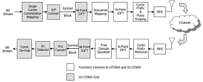
LTE uses a pre-coded version of OFDM called Single Carrier Frequency Division Multiple Access (SC-FDMA) in the uplink. This is to compensate for a drawback with normal OFDM, which has a very high Peak to Average Power Ratio (PAPR).
High PAPR requires expensive and inefficient power amplifiers with high requirements on linearity, which increases the cost of the terminal and drains the battery faster.
SC-FDMA solves this problem by grouping together the resource blocks in such a way that reduces the need for linearity, and so power consumption, in the power amplifier. A low PAPR also improves coverage and the cell-edge performance.


LTE Communication Channels

LTE Communication Channels

The information flows between the different protocols are known as channels and signals. LTE uses several different types of logical, transport and physical channel, which are distinguished by the kind of information they carry and by the way in which the information is processed.
  • Logical Channels : Define whattype of information is transmitted over the air, e.g. traffic channels, control channels, system broadcast, etc. Data and signalling messages are carried on logical channels between the RLC and MAC protocols.
  • Transport Channels : Define howis something transmitted over the air, e.g. what are encoding, interleaving options used to transmit data. Data and signalling messages are carried on transport channels between the MAC and the physical layer.
  • Physical Channels : Define whereis something transmitted over the air, e.g. first N symbols in the DL frame. Data and signalling messages are carried on physical channels between the different levels of the physical layer.

Logical Channels

Logical channels define what type of data is transferred. These channels define the data-transfer services offered by the MAC layer. Data and signalling messages are carried on logical channels between the RLC and MAC protocols.
Logical channels can be divided into control channels and traffic channels. Control Channel can be either common channel or dedicated channel. A common channel means common to all users in a cell (Point to multipoint) while dedicated channels means channels can be used only by one user (Point to Point).
Logical channels are distinguished by the information they carry and can be classified in two ways. Firstly, logical traffic channels carry data in the user plane, while logical control channels carry signalling messages in the control plane. Following table lists the logical channels that are used by LTE:
Channel Name Acronym Control channel Traffic channel
Broadcast Control Channel BCCH X  
Paging Control Channel PCCH X  
Common Control Channel CCCH X  
Dedicated Control Channel DCCH X  
Multicast Control Channel MCCH X  
Dedicated Traffic Channel DTCH   X
Multicast Traffic Channel MTCH   X

Transport Channels

Transport channels define how and with what type of characteristics the data is transferred by the physical layer. Data and signalling messages are carried on transport channels between the MAC and the physical layer.
Transport Channels are distinguished by the ways in which the transport channel processor manipulates them. Following table lists the transport channels that are used by LTE:
Channel Name Acronym Downlink Uplink
Broadcast Channel BCH X  
Downlink Shared Channel DL-SCH X  
Paging Channel PCH X  
Multicast Channel MCH X  
Uplink Shared Channel UL-SCH   X
Random Access Channel RACH   X

Physical Channels

Data and signalling messages are carried on physical channels between the different levels of the physical layer and accordingly they are divided into two parts:
  • Physical Data Channels
  • Physical Control Channels

Physical data channels

Physical data channels are distinguished by the ways in which the physical channel processor manipulates them, and by the ways in which they are mapped onto the symbols and sub-carriers used by Orthogonal frequency-division multiplexing (OFDMA). Following table lists the physical data channels that are used by LTE:
Channel Name Acronym Downlink Uplink
Physical downlink shared channel PDSCH X  
Physical broadcast channel PBCH X  
Physical multicast channel PMCH X  
Physical uplink shared channel PUSCH   X
Physical random access channel PRACH   X
The transport channel processor composes several types of control information, to support the low-level operation of the physical layer. These are listed in the below table:
Field Name Acronym Downlink Uplink
Downlink control information DCI X  
Control format indicator CFI X  
Hybrid ARQ indicator HI X  
Uplink control information UCI   X

Physical Control Channels

The transport channel processor also creates control information that supports the low-level operation of the physical layer and sends this information to the physical channel processor in the form of physical control channels.
The information travels as far as the transport channel processor in the receiver, but is completely invisible to higher layers. Similarly, the physical channel processor creates physical signals, which support the lowest-level aspects of the system.
Physical Control Channels are listed in the below table:
Channel Name Acronym Downlink Uplink
Physical control format indicator channel PCFICH X  
Physical hybrid ARQ indicator channel PHICH X  
Physical downlink control channel PDCCH X  
Relay physical downlink control channel R-PDCCH X  
Physical uplink control channel PUCCH   X
The base station also transmits two other physical signals, which help the mobile acquire the base station after it first switches on. These are known as the primary synchronization signal (PSS) and the secondary synchronization signal (SSS).


LTE Layers Data Flow

LTE Layers Data Flow

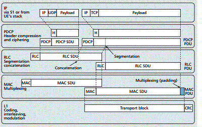
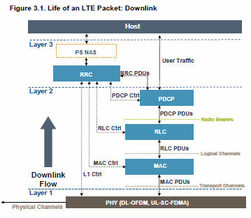
Below is a logical digram of E-UTRAN Protocol layers with a depiction of data flow through various layers:
LTE Layers Data Flow Packets received by a layer are called Service Data Unit (SDU) while the packet output of a layer is referred to by Protocol Data Unit (PDU). Let's see the flow of data from top to bottom:
  • IP Layer submits PDCP SDUs (IP Packets) to the PDCP layer. PDCP layer does header compression and adds PDCP header to these PDCP SDUs. PDCP Layer submits PDCP PDUs (RLC SDUs) to RLC layer.
    PDCP Header Compression : PDCP removes IP header (Minimum 20 bytes) from PDU, and adds Token of 1-4 bytes. Which provides a tremendous savings in the amount of header that would otherwise have to go over the air.
    LTE PDCP SDU
  • RLC layer does segmentation of these SDUS to make the RLC PDUs. RLC adds header based on RLC mode of operation. RLC submits these RLC PDUs (MAC SDUs) to the MAC layer.
    RLC Segmentation : If an RLC SDU is large, or the available radio data rate is low (resulting in small transport blocks), the RLC SDU may be split among several RLC PDUs. If the RLC SDU is small, or the available radio data rate is high, several RLC SDUs may be packed into a single PDU.
  • MAC layer adds header and does padding to fit this MAC SDU in TTI. MAC layer submits MAC PDU to physical layer for transmitting it onto physical channels.
  • Physical channel transmits this data into slots of sub frame.


LTE Protocol Stack Layers

LTE Protocol Stack Layers

Let's have a close look at all the layers available in E-UTRAN Protocol Stack which we have seen in previous chapter. Below is a more ellaborated diagram of E-UTRAN Protocol Stack:
LTE Protocol Layers

Physical Layer (Layer 1)

Physical Layer carries all information from the MAC transport channels over the air interface. Takes care of the link adaptation (AMC), power control, cell search (for initial synchronization and handover purposes) and other measurements (inside the LTE system and between systems) for the RRC layer.

Medium Access Layer (MAC)

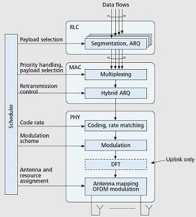
MAC layer is responsible for Mapping between logical channels and transport channels, Multiplexing of MAC SDUs from one or different logical channels onto transport blocks (TB) to be delivered to the physical layer on transport channels, de multiplexing of MAC SDUs from one or different logical channels from transport blocks (TB) delivered from the physical layer on transport channels, Scheduling information reporting, Error correction through HARQ, Priority handling between UEs by means of dynamic scheduling, Priority handling between logical channels of one UE, Logical Channel prioritization.

Radio Link Control (RLC)

RLC operates in 3 modes of operation: Transparent Mode (TM), Unacknowledged Mode (UM), and Acknowledged Mode (AM).
RLC Layer is responsible for transfer of upper layer PDUs, error correction through ARQ (Only for AM data transfer), Concatenation, segmentation and reassembly of RLC SDUs (Only for UM and AM data transfer).
RLC is also responsible for re-segmentation of RLC data PDUs (Only for AM data transfer), reordering of RLC data PDUs (Only for UM and AM data transfer), duplicate detection (Only for UM and AM data transfer), RLC SDU discard (Only for UM and AM data transfer), RLC re-establishment, and protocol error detection (Only for AM data transfer).

Radio Resource Control (RRC)

The main services and functions of the RRC sublayer include broadcast of System Information related to the non-access stratum (NAS), broadcast of System Information related to the access stratum (AS), Paging, establishment, maintenance and release of an RRC connection between the UE and E-UTRAN, Security functions including key management, establishment, configuration, maintenance and release of point to point Radio Bearers.

Packet Data Convergence Control (PDCP)

PDCP Layer is responsible for Header compression and decompression of IP data, Transfer of data (user plane or control plane), Maintenance of PDCP Sequence Numbers (SNs), In-sequence delivery of upper layer PDUs at re-establishment of lower layers, Duplicate elimination of lower layer SDUs at re-establishment of lower layers for radio bearers mapped on RLC AM, Ciphering and deciphering of user plane data and control plane data, Integrity protection and integrity verification of control plane data, Timer based discard, duplicate discarding, PDCP is used for SRBs and DRBs mapped on DCCH and DTCH type of logical channels.

Non Access Stratum (NAS) Protocols

The non-access stratum (NAS) protocols form the highest stratum of the control plane between the user equipment (UE) and MME.
NAS protocols support the mobility of the UE and the session management procedures to establish and maintain IP connectivity between the UE and a PDN GW.


LTE Radio Protocol Architecture

LTE Radio Protocol Architecture

The radio protocol architecture for LTE can be separated into control plane architecture and user plane architecture as shown below:
LTE Radio Protocol Architecture At user plane side, the application creates data packets that are processed by protocols such as TCP, UDP and IP, while in the control plane, the radio resource control (RRC) protocol writes the signalling messages that are exchanged between the base station and the mobile. In both cases, the information is processed by the packet data convergence protocol (PDCP), the radio link control (RLC) protocol and the medium access control (MAC) protocol, before being passed to the physical layer for transmission.

User Plane

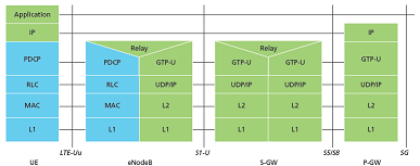
The user plane protocol stack between the e-Node B and UE consists of the following sub-layers:
  • PDCP (Packet Data Convergence Protocol)
  • RLC (radio Link Control)
  • Medium Access Control (MAC)
On the user plane, packets in the core network (EPC) are encapsulated in a specific EPC protocol and tunneled between the P-GW and the eNodeB. Different tunneling protocols are used depending on the interface. GPRS Tunneling Protocol (GTP) is used on the S1 interface between the eNodeB and S-GW and on the S5/S8 interface between the S-GW and P-GW.
LTE User Plane Packets received by a layer are called Service Data Unit (SDU) while the packet output of a layer is referred to by Protocol Data Unit (PDU) and IP packets at user plane flow from top to bottom layers.

Control Plane

The control plane includes additionally the Radio Resource Control layer (RRC) which is responsible for configuring the lower layers.
The Control Plane handles radio-specific functionality which depends on the state of the user equipment which includes two states: idle or connected.
Mode Description
Idle The user equipment camps on a cell after a cell selection or reselection process where factors like radio link quality, cell status and radio access technology are considered. The UE also monitors a paging channel to detect incoming calls and acquire system information. In this mode, control plane protocols include cell selection and reselection procedures.
Connected The UE supplies the E-UTRAN with downlink channel quality and neighbour cell information to enable the E-UTRAN to select the most suitable cell for the UE. In this case, control plane protocol includes the Radio Link Control (RRC) protocol.
The protocol stack for the control plane between the UE and MME is shown below. The grey region of the stack indicates the access stratum (AS) protocols. The lower layers perform the same functions as for the user plane with the exception that there is no header compression function for the control plane.
LTE Control Plane


LTE Numbering & Addressing

LTE Numbering & Addressing

An LTE network area is divided into three different types of geographical areas explained below:
S.N. Area and Description
1 The MME pool areas
This is an area through which the mobile can move without a change of serving MME. Every MME pool area is controlled by one or more MMEs on the network.
2 The S-GW service areas
This is an area served by one or more serving gateways S-GW, through which the mobile can move without a change of serving gateway.
3 The Tracking areas
The MME pool areas and the S-GW service areas are both made from smaller, non-overlapping units known as tracking areas (TAs). They are similar to the location and routing areas from UMTS and GSM and will be used to track the locations of mobiles that are on standby mode.
Thus an LTE network will comprise of many MME pool areas, many S-GW service areas and lots of tracking areas.

The Network IDs

The network itself will be identified using Public Land Mobile Network Identity (PLMN-ID) which will have a three digit mobile country code (MCC) and a two or three digit mobile network code (MNC). For example, the Mobile Country Code for the UK is 234, while Vodafone's UK network uses a Mobile Network Code of 15.
LTE Network ID

The MME IDs

Each MME has three main identities. An MME code (MMEC) uniquely identifies the MME within all the pool areas. A group of MMEs is assigned an MME Group Identity (MMEGI) which works along with MMEC to make MME identifier (MMEI). A MMEI uniquely identifies the MME within a particular network.
LTE MMEI If we combile PLMN-ID with the MMEI then we arrive at a Globally Unique MME Identifier (GUMMEI), which identifies an MME anywhere in the world:
LTE GUMMEI

The Tracking Area IDs

Each tracking area has two main identities. The tracking area code (TAC) identifies a tracking area within a particular network and if we combining this with the PLMN-ID then we arrive at a Globally Unique Tracking Area Identity (TAI).
LTE TAI

The Cell IDs

Each cell in the network has three types of identity. The E-UTRAN cell identity (ECI) identifies a cell within a particular network, while the E-UTRAN cell global identifier (ECGI) identifies a cell anywhere in the world.
The physical cell identity, which is a number from 0 to 503 and it distinguishes a cell from its immediate neighbours.

The Mobile Equipment ID

The international mobile equipment identity (IMEI) is a unique identity for the mobile equipment and the International Mobile Subscriber Identity (IMSI) is a unique identity for the UICC and the USIM.
The M temporary mobile subscriber identity (M-TMSI) identifies a mobile to its serving MME. Adding the MME code in M-TMSI results in a S temporary mobile subscriber identity (S-TMSI), which identifies the mobile within an MME pool area.
LTE S-TMSI Finally adding the MME group identity and the PLMN identity with S-TMSI results in the Globally Unique Temporary Identity (GUTI).
LTE GUTI


LTE Roaming Architecture

LTE Roaming Architecture

A network run by one operator in one country is known as a Public Land Mobile Network (PLMN) and when a subscribed user uses his operator's PLMN then it is said Home-PLMN but roaming allows users to move outside their home network and using the resources from other operator's network. This other network is called Visited-PLMN.
A roaming user is connected to the E-UTRAN, MME and S-GW of the visited LTE network. However, LTE/SAE allows the P-GW of either the visited or the home network to be used, as shown in below:
LTE Roaming Architecture The home network's P-GW allows the user to access the home operator's services even while in a visited network. A P-GW in the visited network allows a "local breakout" to the Internet in the visited network.
The interface between the serving and PDN gateways is known as S5/S8. This has two slightly different implementations, namely S5 if the two devices are in the same network, and S8 if they are in different networks. For mobiles that are not roaming, the serving and PDN gateways can be integrated into a single device, so that the S5/S8 interface vanishes altogether.

LTE Roaming Charging

The complexities of the new charging mechanisms required to support 4G roaming are much more abundant than in a 3G environment. Few words about both pre-paid and post-paid charging for LTE roaming is given below:
  • Prepaid Charging - The CAMEL standard, which enables prepaid services in 3G, is not supported in LTE; therefore, prepaid customer information must be routed back to the home network as opposed to being handled by the local visited network. As a result, operators must rely on new accounting flows to access prepaid customer data, such as through their P-Gateways in both IMS and non-IMS environments or via their CSCF in an IMS environment.
  • Postpaid Charging - Postpaid data-usage charging works the same in LTE as it does in 3G, using versions TAP 3.11 or 3.12. With local breakout of IMS services, TAP 3.12 is required.
Operators do not have the same amount of visibility into subscriber activities as they do in home-routing scenarios in case of local breakout scenarios because subscriber-data sessions are kept within the visited network; therefore, in order for the home operator to capture real-time information on both pre- and postpaid customers, it must establish a Diameter interface between charging systems and the visited network's P-Gateway.
In case of local breakout of ims services scenario, the visited network creates call detail records (CDRs) from the S-Gateway(s), however, these CDRs do not contain all of the information required to create a TAP 3.12 mobile session or messaging event record for the service usage. As a result, operators must correlate the core data network CDRs with the IMS CDRs to create TAP records.


LTE Network Architecture

LTE Network Architecture

The high-level network architecture of LTE is comprised of following three main components:
  • The User Equipment (UE).
  • The Evolved UMTS Terrestrial Radio Access Network (E-UTRAN).
  • The Evolved Packet Core (EPC).
The evolved packet core communicates with packet data networks in the outside world such as the internet, private corporate networks or the IP multimedia subsystem. The interfaces between the different parts of the system are denoted Uu, S1 and SGi as shown below:
LTE Architecture

The User Equipment (UE)

The internal architecture of the user equipment for LTE is identical to the one used by UMTS and GSM which is actually a Mobile Equipment (ME). The mobile equipment comprised of the following important modules:
  • Mobile Termination (MT) : This handles all the communication functions.
  • Terminal Equipment (TE) : This terminates the data streams.
  • Universal Integrated Circuit Card (UICC) : This is also known as the SIM card for LTE equipments. It runs an application known as the Universal Subscriber Identity Module (USIM).
A USIM stores user-specific data very similar to 3G SIM card. This keeps information about the user's phone number, home network identity and security keys etc.

The E-UTRAN (The access network)

The architecture of evolved UMTS Terrestrial Radio Access Network (E-UTRAN) has been illustrated below.
LTE E-UTRAN The E-UTRAN handles the radio communications between the mobile and the evolved packet core and just has one component, the evolved base stations, called eNodeB or eNB. Each eNB is a base station that controls the mobiles in one or more cells. The base station that is communicating with a mobile is known as its serving eNB.
LTE Mobile communicates with just one base station and one cell at a time and there are following two main functions supported by eNB:
  • The eBN sends and receives radio transmissions to all the mobiles using the analogue and digital signal processing functions of the LTE air interface.
  • The eNB controls the low-level operation of all its mobiles, by sending them signalling messages such as handover commands.
Each eBN connects with the EPC by means of the S1 interface and it can also be connected to nearby base stations by the X2 interface, which is mainly used for signalling and packet forwarding during handover.
A home eNB (HeNB) is a base station that has been purchased by a user to provide femtocell coverage within the home. A home eNB belongs to a closed subscriber group (CSG) and can only be accessed by mobiles with a USIM that also belongs to the closed subscriber group.

The Evolved Packet Core (EPC) (The core network)

The architecture of Evolved Packet Core (EPC) has been illustrated below. There are few more components which have not been shown in the diagram to keep it simple. These components are like the Earthquake and Tsunami Warning System (ETWS), the Equipment Identity Register (EIR) and Policy Control and Charging Rules Function (PCRF).
LTE EPC Below is a brief description of each of the components shown in the above architecture:
  • The Home Subscriber Server (HSS) component has been carried forward from UMTS and GSM and is a central database that contains information about all the network operator's subscribers.
  • The Packet Data Network (PDN) Gateway (P-GW) communicates with the outside world ie. packet data networks PDN, using SGi interface. Each packet data network is identified by an access point name (APN). The PDN gateway has the same role as the GPRS support node (GGSN) and the serving GPRS support node (SGSN) with UMTS and GSM.
  • The serving gateway (S-GW) acts as a router, and forwards data between the base station and the PDN gateway.
  • The mobility management entity (MME) controls the high-level operation of the mobile by means of signalling messages and Home Subscriber Server (HSS).
  • The Policy Control and Charging Rules Function (PCRF) is a component which is not shown in the above diagram but it is responsible for policy control decision-making, as well as for controlling the flow-based charging functionalities in the Policy Control Enforcement Function (PCEF), which resides in the P-GW.
The interface between the serving and PDN gateways is known as S5/S8. This has two slightly different implementations, namely S5 if the two devices are in the same network, and S8 if they are in different networks.

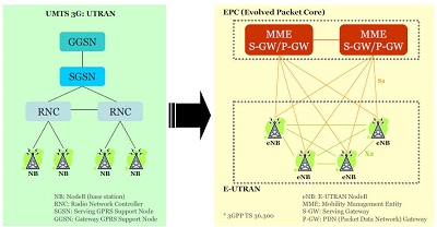
Functional split between the E-UTRAN and the EPC

Following diagram shows the functional split between the E-UTRAN and the EPC for an LTE network:
LTE E-UTRAN and EPC

2G/3G Versus LTE

Following table compares various important Network Elements & Signaling protocols used in 2G/3G abd LTE.
2G/3G LTE
GERAN and UTRAN E-UTRAN
SGSN/PDSN-FA S-GW
GGSN/PDSN-HA PDN-GW
HLR/AAA HSS
VLR MME
SS7-MAP/ANSI-41/RADIUS Diameter
DiameterGTPc-v0 and v1 GTPc-v2
MIP PMIP


LTE INTRODUCTION

INTRODUCTION TO LTE.......

LTE stands for Long Term Evolution and it was started as a project in 2004 by telecommunication body known as the Third Generation Partnership Project (3GPP). SAE (System Architecture Evolution) is the corresponding evolution of the GPRS/3G packet core network evolution. The term LTE is typically used to represent both LTE and SAE.


LTE evolved from an earlier 3GPP system known as the Universal Mobile Telecommunication System (UMTS), which in turn evolved from the Global System for Mobile Communications (GSM). Even related specifications were formally known as the evolved UMTS terrestrial radio access (E-UTRA) and evolved UMTS terrestrial radio access network (E-UTRAN). First version of LTE was documented in Release 8 of the 3GPP specifications.
A rapid increase of mobile data usage and emergence of new applications such as MMOG (Multimedia Online Gaming), mobile TV, Web 2.0, streaming contents have motivated the 3rd Generation Partnership Project (3GPP) to work on the Long-Term Evolution (LTE) on the way towards fourth-generation mobile.
The main goal of LTE is to provide a high data rate, low latency and packet optimized radioaccess technology supporting flexible bandwidth deployments. Same time its network architecture has been designed with the goal to support packet-switched traffic with seamless mobility and great quality of service.

LTE Evolution

Year Event
Mar 2000 Release 99 - UMTS/WCDMA
Mar 2002 Rel 5 - HSDPA
Mar 2005 Rel 6 - HSUPA
Year 2007 Rel 7 - DL MIMO, IMS (IP Multimedia Subsystem)
November 2004 Work started on LTE specification
January 2008 Spec finalized and approved with Release 8
2010 Targeted first deployment

Facts about LTE

  • LTE is the successor technology not only of UMTS but also of CDMA 2000.
  • LTE is important because it will bring up to 50 times performance improvement and much better spectral efficiency to cellular networks.
  • LTE introduced to get higher data rates, 300Mbps peak downlink and 75 Mbps peak uplink. In a 20MHz carrier, data rates beyond 300Mbps can be achieved under very good signal conditions.
  • LTE is an ideal technology to support high date rates for the services such as voice over IP (VOIP), streaming multimedia, videoconferencing or even a high-speed cellular modem.
  • LTE uses both Time Division Duplex (TDD) and Frequency Division Duplex (FDD) mode. In FDD uplink and downlink transmission used different frequency, while in TDD both uplink and downlink use the same carrier and are separated in Time.
  • LTE supports flexible carrier bandwidths, from 1.4 MHz up to 20 MHz as well as both FDD and TDD. LTE designed with a scalable carrier bandwidth from 1.4 MHz up to 20 MHz which bandwidth is used depends on the frequency band and the amount of spectrum available with a network operator.
  • All LTE devices have to support (MIMO) Multiple Input Multiple Output transmissions, which allow the base station to transmit several data streams over the same carrier simultaneously.
  • All interfaces between network nodes in LTE are now IP based, including the backhaul connection to the radio base stations. This is great simplification compared to earlier technologies that were initially based on E1/T1, ATM and frame relay links, with most of them being narrowband and expensive.
  • Quality of Service (QoS) mechanism have been standardized on all interfaces to ensure that the requirement of voice calls for a constant delay and bandwidth, can still be met when capacity limits are reached.
  • Works with GSM/EDGE/UMTS systems utilizing existing 2G and 3G spectrum and new spectrum. Supports hand-over and roaming to existing mobile networks.

Advantages of LTE

  • High throughput: High data rates can be achieved in both downlink as well as uplink. This causes high throughput.
  • Low latency: Time required to connect to the network is in range of a few hundred milliseconds and power saving states can now be entered and exited very quickly.
  • FDD and TDD in the same platform: Frequency Division Duplex (FDD) and Time Division Duplex (FDD), both schemes can be used on same platform.
  • Superior end-user experience: Optimized signaling for connection establishment and other air interface and mobility management procedures have further improved the user experience. Reduced latency (to 10 ms) for better user experience.
  • Seamless Connection: LTE will also support seamless connection to existing networks such as GSM, CDMA and WCDMA.
  • Plug and play: The user does not have to manually install drivers for the device. Instead system automatically recognizes the device, loads new drivers for the hardware if needed, and begins to work with the newly connected device.
  • Simple architecture: Because of Simple architecture low operating expenditure (OPEX).

LTE - QoS

LTE architecture supports hard QoS, with end-to-end quality of service and guaranteed bit rate (GBR) for radio bearers. Just as Ethernet and the internet have different types of QoS, for example, various levels of QoS can be applied to LTE traffic for different applications. Because the LTE MAC is fully scheduled, QoS is a natural fit.
Evolved Packet System (EPS) bearers provide one-to-one correspondence with RLC radio bearers and provide support for Traffic Flow Templates (TFT). There are four types of EPS bearers:
  • GBR Bearer resources permanently allocated by admission control
  • Non-GBR Bearer no admission control
  • Dedicated Bearer associated with specific TFT (GBR or non-GBR)
  • Default Bearer Non GBR, catch-all for unassigned traffic

LTE PARAMITERS

This section will summarize the Basic parameters of the LTE:
Parameters Description
Frequency range UMTS FDD bands and TDD bands defined in 36.101(v860) Table 5.5.1, given below
Duplexing FDD, TDD, half-duplex FDD
Channel coding Turbo code
Mobility 350 km/h
Channel Bandwidth (MHz)
  • 1.4
  • 3
  • 5
  • 10
  • 15
  • 20
Transmission Bandwidth Configuration NRB : (1 resource block = 180kHz in 1ms TTI )
  • 6
  • 15
  • 25
  • 50
  • 75
  • 100
Modulation Schemes UL: QPSK, 16QAM, 64QAM(optional)

DL: QPSK, 16QAM, 64QAM
Multiple Access Schemes UL: SC-FDMA (Single Carrier Frequency Division Multiple Access) supports 50Mbps+ (20MHz spectrum)

DL: OFDM (Orthogonal Frequency Division Multiple Access) supports 100Mbps+ (20MHz spectrum)
Multi-Antenna Technology UL: Multi-user collaborative MIMO

DL: TxAA, spatial multiplexing, CDD ,max 4x4 array
Peak data rate in LTE UL: 75Mbps(20MHz bandwidth)

DL: 150Mbps(UE Category 4, 2x2 MIMO, 20MHz bandwidth)

DL: 300Mbps(UE category 5, 4x4 MIMO, 20MHz bandwidth)
MIMO
(Multiple Input Multiple Output)
UL: 1 x 2, 1 x 4

DL: 2 x 2, 4 x 2, 4 x 4
Coverage 5 - 100km with slight degradation after 30km
QoS E2E QOS allowing prioritization of different class of service
Latency End-user latency < 10mS

E-UTRA Operating Bands

Following is the table for E-UTRA operating bands taken from LTE Sepecification 36.101(v860) Table 5.5.1:
E-UTRA Table 5.5.1
Add caption