Tuesday, 8 March 2016

Introducing LTE-Advanced

Introducing LTE-Advanced

Application Note
LTE-Advanced (LTE-A) is the project name of the evolved version of LTE that is
being developed by 3GPP. LTE-A will meet or exceed the requirements of the
International Telecommunication Union (ITU) for the fourth generation (4G) radio
communication standard known as IMT-Advanced. LTE-Advanced is being speci-
fied initially as part of Release 10 of the 3GPP specifications, with a functional
freeze targeted for March 2011. The LTE specifications will continue to be
developed in subsequent 3GPP releases.
In October 2009, the 3GPP Partners formally submitted LTE-Advanced to the
ITU Radiocommunication sector (ITU-R) as a candidate for 4G IMT-Advanced [1].
Publication by the ITU of the specification for IMT-Advanced is expected by
March 2011. As more and more wireless operators announce plans to deploy
LTE in their next-generation networks, interest in LTE-Advanced is growing.
This application note covers the following topics:
• Summary of the ITU requirements for 4G
• Summary of 3GPP requirements for LTE-Advanced, including the expected
timeline
• Key solution proposals for LTE-Advanced
• Release 10 and beyond: Technologies under consideration
• Anticipated design and test challenges
The application note also introduces Agilent’s LTE-Advanced design and test
solutions that are ready for use by early adopters. These solutions will be con-
tinuously enhanced as the LTE-Advanced specifications are released.


Monday, 7 March 2016

LTE Advanced (LTE+)

With the standards definitions now available for LTE, the Long Term Evolution of the 3G services, eyes are now turning towards the next development, that of the truly 4G technology named IMT Advanced. The new technology being developed under the auspices of 3GPP to meet these requirements is often termed LTE Advanced.
In order that the cellular telecommunications technology is able to keep pace with technologies that may compete, it is necessary to ensure that new cellular technologies are being formulated and developed. This is the reasoning behind starting the development of the new LTE Advanced systems, proving the technology and developing the LTE Advanced standards.

Typical cellphone handsets that can operate on a 4G LTE-Advanced network
In order that the correct solution is adopted for the 4G system, the ITU-R (International Telecommunications Union - Radiocommunications sector) has started its evaluation process to develop the recommendations for the terrestrial components of the IMT Advanced radio interface. One of the main competitors for this is the LTE Advanced solution.
One of the key milestones is October 2010 when the ITU-R decides the framework and key characteristics for the IMT Advanced standard. Before this, the ITU-R will undertake the evaluation of the various proposed radio interface technologies of which LTE Advanced is a major contender.

Key milestones for ITU-R IMT Advanced evaluation

The ITU-R has set a number of milestones to ensure that the evaluation of IMT Advanced technologies occurs in a timely fashion. A summary of the main milestones is given below and this defines many of the overall timescales for the development of IMT Advanced and in this case LTE Advanced as one of the main technologies to be evaluated.

Key Milestones on the Development of 4G LTE-Advanced
Milestone Date
Issue invitation to propose Radio Interface Technologies. March 2008
ITU date for cut-off for submission of proposed Radio Interface Technologies. October 2009
Cutoff date for evaluation report to ITU. June 2010
Decision on framework of key characteristics of IMT Advanced Radio Interface Technologies. October 2010
Completion of development of radio interface specification recommendations. February 2011

LTE Advanced development history

With 3G technology established, it was obvious that the rate of development of cellular technology should not slow. As a result initial ideas for the development of a new 4G system started to be investigated. In one early investigation which took place on 25 December 2006 with information released to the press on 9 February 2007, NTT DoCoMo detailed information about trials in which they were able to send data at speeds up to approximately 5 Gbit/s in the downlink within a 100MHz bandwidth to a mobile station moving at 10km/h. The scheme used several technologies to achieve this including variable spreading factor spread orthogonal frequency division multiplex, MIMO, multiple input multiple output, and maximum likelihood detection. Details of these new 4G trials were passed to 3GPP for their consideration
In 2008 3GPP held two workshops on IMT Advanced, where the "Requirements for Further Advancements for E-UTRA" were gathered. The resulting Technical Report 36.913 was then published in June 2008 and submitted to the ITU-R defining the LTE-Advanced system as their proposal for IMT-Advanced.
The development of LTE Advanced / IMT Advanced can be seen to follow and evolution from the 3G services that were developed using UMTS / W-CDMA technology.

Comparison of LTE-A with other Cellular Technologies
  WCDMA
(UMTS)
HSPA
HSDPA / HSUPA
HSPA+ LTE LTE Advanced
(IMT Advanced)
Max downlink speed
bps
384 k 14 M 28 M 100M 1G
Max uplink speed
bps
128 k 5.7 M 11 M 50 M 500 M
Latency
round trip time
approx
150 ms 100 ms 50ms (max) ~10 ms less than 5 ms
3GPP releases Rel 99/4 Rel 5 / 6 Rel 7 Rel 8 Rel 10
Approx years of initial roll out 2003 / 4 2005 / 6 HSDPA
2007 / 8 HSUPA
2008 / 9 2009 / 10 2014 / 15
Access methodology CDMA CDMA CDMA OFDMA / SC-FDMA OFDMA / SC-FDMA
LTE Advanced is not the only candidate technology. WiMAX is also there, offering very high data rates and high levels of mobility. However it now seems less likely that WiMAX will be adopted as the 4G technology, with LTE Advanced appearing to be better positioned.

LTE Advanced key features

With work starting on LTE Advanced, a number of key requirements and key features are coming to light. Although not fixed yet in the specifications, there are many high level aims for the new LTE Advanced specification. These will need to be verified and much work remains to be undertaken in the specifications before these are all fixed. Currently some of the main headline aims for LTE Advanced can be seen below:
  1. Peak data rates: downlink - 1 Gbps; uplink - 500 Mbps.
  2. Spectrum efficiency: 3 times greater than LTE.
  3. Peak spectrum efficiency: downlink - 30 bps/Hz; uplink - 15 bps/Hz.
  4. Spectrum use: the ability to support scalable bandwidth use and spectrum aggregation where non-contiguous spectrum needs to be used.
  5. Latency: from Idle to Connected in less than 50 ms and then shorter than 5 ms one way for individual packet transmission.
  6. Cell edge user throughput to be twice that of LTE.
  7. Average user throughput to be 3 times that of LTE.
  8. Mobility: Same as that in LTE
  9. Compatibility: LTE Advanced shall be capable of interworking with LTE and 3GPP legacy systems.
These are many of the development aims for LTE Advanced. Their actual figures and the actual implementation of them will need to be worked out during the specification stage of the system.

LTE Advanced technologies

There are a number of key technologies that will enable LTE Advanced to achieve the high data throughput rates that are required. MIMO and OFDM are two of the base technologies that will be enablers. Along with these there are a number of other techniques and technologies that will be employed.
  • Orthogonal Frequency Division Multiplex, OFDM   OFDM forms the basis of the radio bearer. Along with it there is OFDMA (Orthogonal Frequency Division Multiple Access) along with SC-FDMA (Single Channel Orthogonal Frequency Division Multiple Access). These will be used in a hybrid format. However the basis for all of these access schemes is OFDM.

    Note on OFDM:

    Orthogonal Frequency Division Multiplex (OFDM) is a form of transmission that uses a large number of close spaced carriers that are modulated with low rate data. Normally these signals would be expected to interfere with each other, but by making the signals orthogonal to each other there is no mutual interference. The data to be transmitted is split across all the carriers to give resilience against selective fading from multi-path effects..
    Click on the link for an OFDM tutorial

  • Multiple Input Multiple Output, MIMO:   One of the other key enablers for LTE Advanced that is common to LTE is MIMO. This scheme is also used by many other technologies including WiMAX and Wi-Fi - 802.11n. MIMO - Multiple Input Multiple Output enables the data rates achieved to be increased beyond what the basic radio bearer would normally allow.

    Note on MIMO:

    Two major limitations in communications channels can be multipath interference, and the data throughput limitations as a result of Shannon's Law. MIMO provides a way of utilising the multiple signal paths that exist between a transmitter and receiver to significantly improve the data throughput available on a given channel with its defined bandwidth. By using multiple antennas at the transmitter and receiver along with some complex digital signal processing, MIMO technology enables the system to set up multiple data streams on the same channel, thereby increasing the data capacity of a channel.
    Click on the link for a MIMO tutorial


    For LTE Advanced, the use of MIMO is likely to involve further and more advanced techniques including the use of additional antennas in the matrix to enable additional paths to be used, although as the number of antennas increases, the overhead increases and the return per additional path is less.

    In additional to the numbers of antennas increasing, it is likely that techniques such as beamforming may be used to enable the antenna coverage to be focused where it is needed.
  • Carrier Aggregation, CA:   As many operators do not have sufficient contiguous spectrum to provide the required bandwidths for the very high data rates, a scheme known as carrier aggregation has been developed. Using this technology operators are able to utilise multiple channels either in the same bands or different areas of the spectrum to provide the required bandwidth. Read more about Carrier Aggregation, CA
  • Coordinated Multipoint :   One of the key issues with many cellular systems is that of poor performance at the cell edges. Interference from adjacent cells along with poor signal quality lead to a reduction in data rates. For LTE-Advanced a scheme known as coordinated multipoint has been introduced. Read more about Coordinated Multipoint, CoMP
  • LTE Relaying:   LTE relaying is a scheme that enables signals to be forwarded by remote stations from a main base station to improve coverage. Read more about LTE Relaying
  • Device to Device, D2D:   LTE D2D is a facility that has been requested by a number of users, in particular the emergency services. It enables fast swift access via direct communication - a facility that is essential for the emergency services when they may be on the scene of an incident. Read more about Device to Device communications

LTE Technology Leyers

LTE video tutorial


LTE physical layer


Introduction to LTE architecture


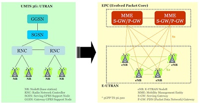
LTE network architecture

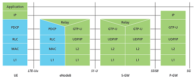
E-UTRAN user plance protocol stack

EPS architecture overview

This excellent video by Russell DeLong covers the EPS in detail. The topics covered here are:
Terminology clarifications for "4G LTE" and the EPS.
Overview of each component of EPS. Russell walks you through the role of the MME, the S-GW and the P-GW.
Overview of each logical connection between each component on the EPS.

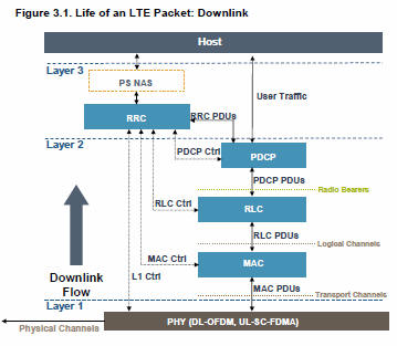
LTE channels and protocol layers


LTE physical layer presentation


Thursday, 3 March 2016

LTE ( 4G ) Optimisation and R&d: LTE INTRODUCTION

LTE ( 4G ) Optimisation and R&d: LTE INTRODUCTION: INTRODUCTION TO LTE....... LTE stands for Long Term Evolution and it was started as a project in 2004 by telecommunication body kno...

Wednesday, 2 March 2016

LTE Glossary

LTE Glossary

Term Description
3GPP 3rd Generation Partnership Project
3GPP2 3rd Generation Partnership Project 2
ARIB Association of Radio Industries and Businesses
ATIS Alliance for Telecommunication Industry Solutions
AWS Advanced Wireless Services
CAPEX Capital Expenditure
CCSA China Communications Standards Association
CDMA Code Division Multiple Access
CDMA2000 Code Division Multiple Access 2000
DAB Digital Audio Broadcast
DSL Digital Subscriber Line
DVB Digital Video Broadcast
eHSPA evolved High Speed Packet Access
ETSI European Telecommunications Standards Institute
FDD Frequency Division Duplex
FWT Fixed Wireless Terminal
GSM Global System for Mobile communication
HSPA High Speed Packet Access
HSS Home Subscriber Server
IEEE Institute of Electrical and Electronics Engineers
IPTV Internet Protocol Television
LTE Long Term Evolution
MBMS Multimedia Broadcast Multicast Service
MIMO Multiple Input Multiple Output
MME Mobility Management Entity
NGMN Next Generation Mobile Networks
OFDM Orthogonal Frequency Division Multiplexing
OPEX Operational Expenditure
PAPR Peak to Average Power Ratio
PCI Peripheral Component Interconnect
PCRF Policing and Charging Rules Function
PDSN Packet Data Serving Node
PS Packet Switched
QoS Quality of Service
RAN Radio Access Network
SAE System Architecture Evolution
SC-FDMA Single Carrier Frequency Division Multiple Access
SGSN Serving GPRS Support Node
TDD Time Division Duplex
TTA Telecommunications Technology Association
TTC Telecommunication Technology Committee
TTI Transmission Time Interval
UTRA Universal Terrestrial Radio Access
UTRAN Universal Terrestrial Radio Access Network
WCDMA Wideband Code Division Multiple Access
WLAN Wireless Local Area Network


LTE OFDM Technology

LTE OFDM Technology

To overcome the effect of multi path fading problem available in UMTS, LTE uses Orthogonal Frequency Division Multiplexing (OFDM) for the downlink - that is, from the base station to the terminal to transmit the data over many narrow band careers of 180 KHz each instead of spreading one signal over the complete 5MHz career bandwidth ie. OFDM uses a large number of narrow sub-carriers for multi-carrier transmission to carry data.
Orthogonal frequency-division multiplexing (OFDM), is a frequency-division multiplexing (FDM) scheme used as a digital multi-carrier modulation method.
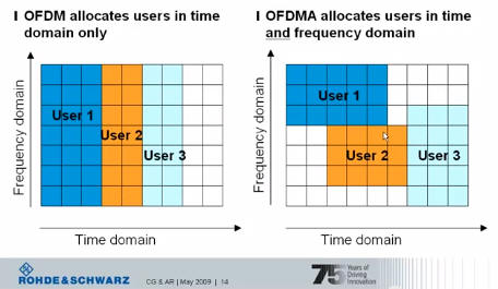
OFDM meets the LTE requirement for spectrum flexibility and enables cost-efficient solutions for very wide carriers with high peak rates. The basic LTE downlink physical resource can be seen as a time-frequency grid, as illustrated in Figure below:
The OFDM symbols are grouped into resource blocks. The resource blocks have a total size of 180kHz in the frequency domain and 0.5ms in the time domain. Each 1ms Transmission Time Interval (TTI) consists of two slots (Tslot).
LTE OFDM Each user is allocated a number of so-called resource blocks in the time.frequency grid. The more resource blocks a user gets, and the higher the modulation used in the resource elements, the higher the bit-rate. Which resource blocks and how many the user gets at a given point in time depend on advanced scheduling mechanisms in the frequency and time dimensions.
The scheduling mechanisms in LTE are similar to those used in HSPA, and enable optimal performance for different services in different radio environments.

Advantages of OFDM

  • The primary advantage of OFDM over single-carrier schemes is its ability to cope with severe channel conditions (for example, attenuation of high frequencies in a long copper wire, narrowband interference and frequency-selective fading due to multipath) without complex equalization filters.
  • Channel equalization is simplified because OFDM may be viewed as using many slowly-modulated narrowband signals rather than one rapidly-modulated wideband signal.
  • The low symbol rate makes the use of a guard interval between symbols affordable, making it possible to eliminate inter symbol interference (ISI).
  • This mechanism also facilitates the design of single frequency networks (SFNs), where several adjacent transmitters send the same signal simultaneously at the same frequency, as the signals from multiple distant transmitters may be combined constructively, rather than interfering as would typically occur in a traditional single-carrier system.

Drawbacks of OFDM

  • High peak-to-average ratio
  • Sensitive to frequency offset, hence to Doppler-shift as well

SC-FDMA Technology

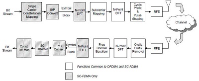
LTE uses a pre-coded version of OFDM called Single Carrier Frequency Division Multiple Access (SC-FDMA) in the uplink. This is to compensate for a drawback with normal OFDM, which has a very high Peak to Average Power Ratio (PAPR).
High PAPR requires expensive and inefficient power amplifiers with high requirements on linearity, which increases the cost of the terminal and drains the battery faster.
SC-FDMA solves this problem by grouping together the resource blocks in such a way that reduces the need for linearity, and so power consumption, in the power amplifier. A low PAPR also improves coverage and the cell-edge performance.


LTE Communication Channels

LTE Communication Channels

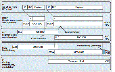
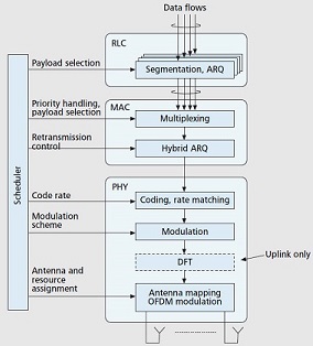
The information flows between the different protocols are known as channels and signals. LTE uses several different types of logical, transport and physical channel, which are distinguished by the kind of information they carry and by the way in which the information is processed.
  • Logical Channels : Define whattype of information is transmitted over the air, e.g. traffic channels, control channels, system broadcast, etc. Data and signalling messages are carried on logical channels between the RLC and MAC protocols.
  • Transport Channels : Define howis something transmitted over the air, e.g. what are encoding, interleaving options used to transmit data. Data and signalling messages are carried on transport channels between the MAC and the physical layer.
  • Physical Channels : Define whereis something transmitted over the air, e.g. first N symbols in the DL frame. Data and signalling messages are carried on physical channels between the different levels of the physical layer.

Logical Channels

Logical channels define what type of data is transferred. These channels define the data-transfer services offered by the MAC layer. Data and signalling messages are carried on logical channels between the RLC and MAC protocols.
Logical channels can be divided into control channels and traffic channels. Control Channel can be either common channel or dedicated channel. A common channel means common to all users in a cell (Point to multipoint) while dedicated channels means channels can be used only by one user (Point to Point).
Logical channels are distinguished by the information they carry and can be classified in two ways. Firstly, logical traffic channels carry data in the user plane, while logical control channels carry signalling messages in the control plane. Following table lists the logical channels that are used by LTE:
Channel Name Acronym Control channel Traffic channel
Broadcast Control Channel BCCH X  
Paging Control Channel PCCH X  
Common Control Channel CCCH X  
Dedicated Control Channel DCCH X  
Multicast Control Channel MCCH X  
Dedicated Traffic Channel DTCH   X
Multicast Traffic Channel MTCH   X

Transport Channels

Transport channels define how and with what type of characteristics the data is transferred by the physical layer. Data and signalling messages are carried on transport channels between the MAC and the physical layer.
Transport Channels are distinguished by the ways in which the transport channel processor manipulates them. Following table lists the transport channels that are used by LTE:
Channel Name Acronym Downlink Uplink
Broadcast Channel BCH X  
Downlink Shared Channel DL-SCH X  
Paging Channel PCH X  
Multicast Channel MCH X  
Uplink Shared Channel UL-SCH   X
Random Access Channel RACH   X

Physical Channels

Data and signalling messages are carried on physical channels between the different levels of the physical layer and accordingly they are divided into two parts:
  • Physical Data Channels
  • Physical Control Channels

Physical data channels

Physical data channels are distinguished by the ways in which the physical channel processor manipulates them, and by the ways in which they are mapped onto the symbols and sub-carriers used by Orthogonal frequency-division multiplexing (OFDMA). Following table lists the physical data channels that are used by LTE:
Channel Name Acronym Downlink Uplink
Physical downlink shared channel PDSCH X  
Physical broadcast channel PBCH X  
Physical multicast channel PMCH X  
Physical uplink shared channel PUSCH   X
Physical random access channel PRACH   X
The transport channel processor composes several types of control information, to support the low-level operation of the physical layer. These are listed in the below table:
Field Name Acronym Downlink Uplink
Downlink control information DCI X  
Control format indicator CFI X  
Hybrid ARQ indicator HI X  
Uplink control information UCI   X

Physical Control Channels

The transport channel processor also creates control information that supports the low-level operation of the physical layer and sends this information to the physical channel processor in the form of physical control channels.
The information travels as far as the transport channel processor in the receiver, but is completely invisible to higher layers. Similarly, the physical channel processor creates physical signals, which support the lowest-level aspects of the system.
Physical Control Channels are listed in the below table:
Channel Name Acronym Downlink Uplink
Physical control format indicator channel PCFICH X  
Physical hybrid ARQ indicator channel PHICH X  
Physical downlink control channel PDCCH X  
Relay physical downlink control channel R-PDCCH X  
Physical uplink control channel PUCCH   X
The base station also transmits two other physical signals, which help the mobile acquire the base station after it first switches on. These are known as the primary synchronization signal (PSS) and the secondary synchronization signal (SSS).