Google's Project SkyBender aims to beam 5G internet from solar-powered drones

Millimeter waves are thought to be the future of high-speed data transmission technology, and may form the backbone of 5G mobile networks. Aereo founder Chet Kanojia's new startup Starry announced earlier this week it would use millimeter wave tech to bring gigabit internet speeds to people's homes via Wi-Fi. Millimeter waves have much shorter range than current smartphone signals and are easily disrupted by weather conditions like rain, fog, and snow. Using what's called a phased array, however, Google and others could potentially focus the transmissions over greater distances.
Google is using millimeter wave technology to achieve 5G speeds
Google is currently testing the technique with a new solar-powered drone called Centaur and other units made by a division known as Google Titan, which the company formed after it acquired drone maker Titan Aerospace in 2014. The company has a deal with the FCC to continue testing until July, according to The Guardian. It's also paying Virgin Galactic about $1,000 a day to use its hanger, as well as an additional $300,000 to Spaceport America to construct installations with servers, millimeter wave transceivers, and other tech onsite.
Google has noted in the past how it plans to compete with other tech giants like Facebook to bring internet access to developing countries. The Guardian says SkyBender is technically part of Google Access, a division that houses Project Loon, Google's air balloon Wi-Fi project aimed at a similar goal of bringing remote parts of the world online. Google did not respond to a request for comment.

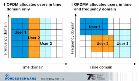
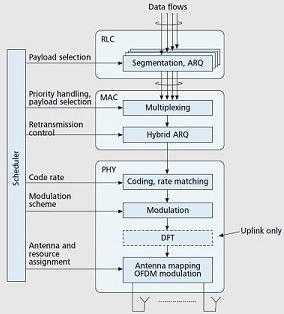
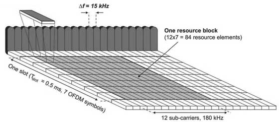 Each user is allocated a number of so-called resource blocks in the
time.frequency grid. The more resource blocks a user gets, and the
higher the modulation used in the resource elements, the higher the
bit-rate. Which resource blocks and how many the user gets at a given
point in time depend on advanced scheduling mechanisms in the frequency
and time dimensions.
Each user is allocated a number of so-called resource blocks in the
time.frequency grid. The more resource blocks a user gets, and the
higher the modulation used in the resource elements, the higher the
bit-rate. Which resource blocks and how many the user gets at a given
point in time depend on advanced scheduling mechanisms in the frequency
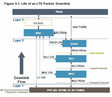
and time dimensions.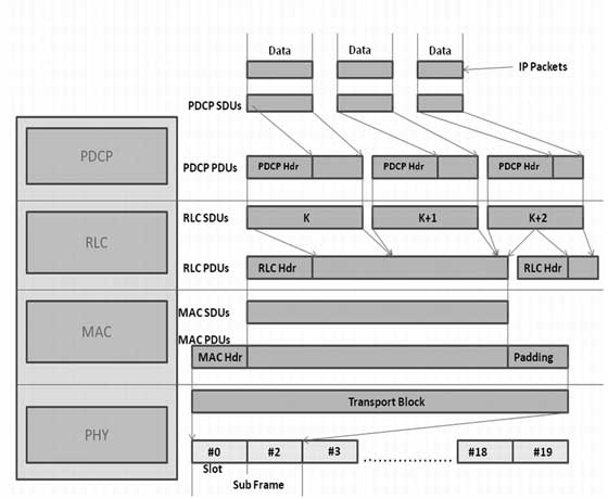 Packets received by a layer are called Service Data Unit (SDU) while
the packet output of a layer is referred to by Protocol Data Unit (PDU).
Let's see the flow of data from top to bottom:
Packets received by a layer are called Service Data Unit (SDU) while
the packet output of a layer is referred to by Protocol Data Unit (PDU).
Let's see the flow of data from top to bottom:
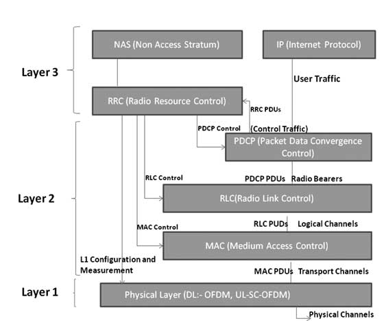
 At user plane side, the application creates data packets that are
processed by protocols such as TCP, UDP and IP, while in the control
plane, the radio resource control (RRC) protocol writes the signalling
messages that are exchanged between the base station and the mobile. In
both cases, the information is processed by the packet data convergence
protocol (PDCP), the radio link control (RLC) protocol and the medium
access control (MAC) protocol, before being passed to the physical layer
for transmission.
At user plane side, the application creates data packets that are
processed by protocols such as TCP, UDP and IP, while in the control
plane, the radio resource control (RRC) protocol writes the signalling
messages that are exchanged between the base station and the mobile. In
both cases, the information is processed by the packet data convergence
protocol (PDCP), the radio link control (RLC) protocol and the medium
access control (MAC) protocol, before being passed to the physical layer
for transmission.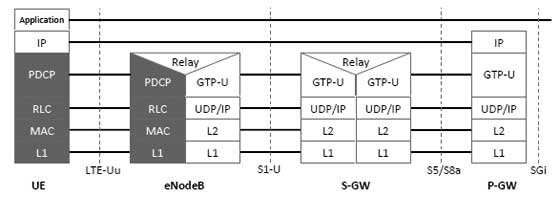 Packets received by a layer are called Service Data Unit (SDU) while
the packet output of a layer is referred to by Protocol Data Unit (PDU)
and IP packets at user plane flow from top to bottom layers.
Packets received by a layer are called Service Data Unit (SDU) while
the packet output of a layer is referred to by Protocol Data Unit (PDU)
and IP packets at user plane flow from top to bottom layers.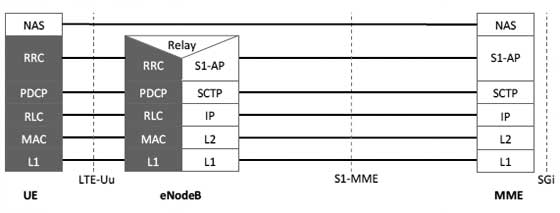
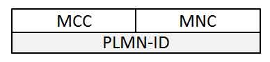
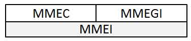 If we combile PLMN-ID with the MMEI then we arrive at a Globally
Unique MME Identifier (GUMMEI), which identifies an MME anywhere in the
world:
If we combile PLMN-ID with the MMEI then we arrive at a Globally
Unique MME Identifier (GUMMEI), which identifies an MME anywhere in the
world: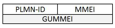
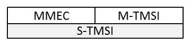 Finally adding the MME group identity and the PLMN identity with
S-TMSI results in the Globally Unique Temporary Identity (GUTI).
Finally adding the MME group identity and the PLMN identity with
S-TMSI results in the Globally Unique Temporary Identity (GUTI).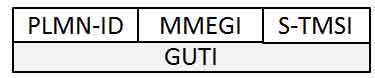
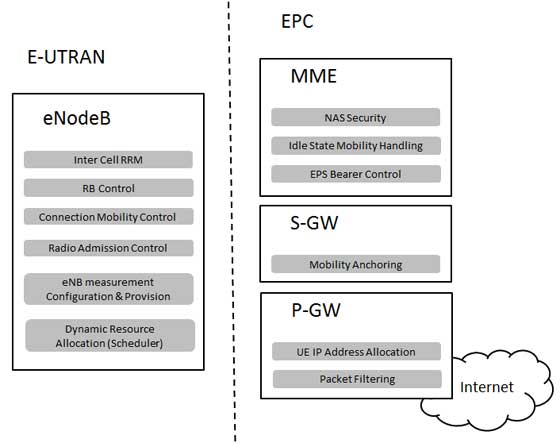
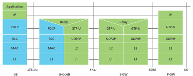
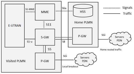 The home network's P-GW allows the user to access the home operator's
services even while in a visited network. A P-GW in the visited network
allows a "local breakout" to the Internet in the visited network.
The home network's P-GW allows the user to access the home operator's
services even while in a visited network. A P-GW in the visited network
allows a "local breakout" to the Internet in the visited network.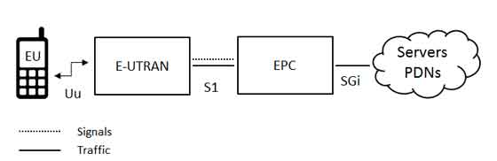
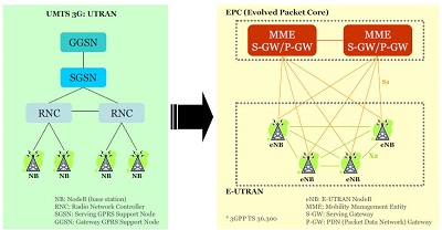
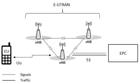 The E-UTRAN handles the radio communications between the mobile and
the evolved packet core and just has one component, the evolved base
stations, called eNodeB or eNB. Each eNB is a base station
that controls the mobiles in one or more cells. The base station that
is communicating with a mobile is known as its serving eNB.
The E-UTRAN handles the radio communications between the mobile and
the evolved packet core and just has one component, the evolved base
stations, called eNodeB or eNB. Each eNB is a base station
that controls the mobiles in one or more cells. The base station that
is communicating with a mobile is known as its serving eNB.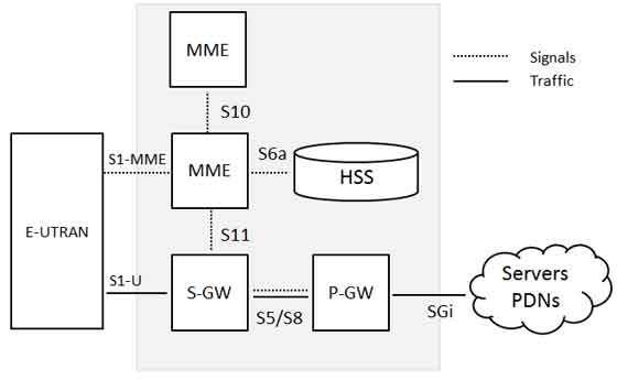 Below is a brief description of each of the components shown in the above architecture: